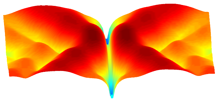
This research project has developed a means of particle manipulation using an applied ultrasonic field as shown in the video below.
Ultrasonics and Instrumentation
Microbubble Acoustic Trap
The video above shows particles flowing from right to left in a cellulose tube. These particles are then 'held' in a low pressure region at the left-hand side of the video. When the aggregate of bubbles becomes too great the trapping force is not sufficient to hold the microbubble collection and they eventually move away. However, a new accumulation of particles then begins.
Acoustic Trap: Manipulation of microparticles using an acoustic beam
The acoustic trap technology has potential to assist in applications such as therapeutic drug delivery or theranostics, and for particle filtering.
The acoustic trap operates like so. Particles such as encapsulated microbubbles (1 - 10 µm diameter) flow along a tube located perpendicular to an ultrasonic beam (in this case from right to left).
A focused ultrasonic beam is generated using a linear array transducer in conjunction with the University of Leeds UARP (Ultrasound Array Research Platform) system.
Particle trapping is achieved by creating a pressure null or low pressure region at the focal point as shown below.

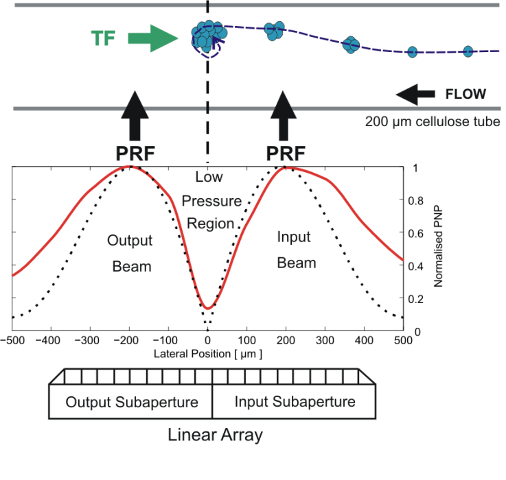
This pressure null is generated by splitting the array aperture into two parts and transmitting two focused beams.
The figure below shows a diagram of microbubbles collecting, with the simulated lateral pressure profile (dotted line) and a comparative hydrophone measurement (red line) also shown.

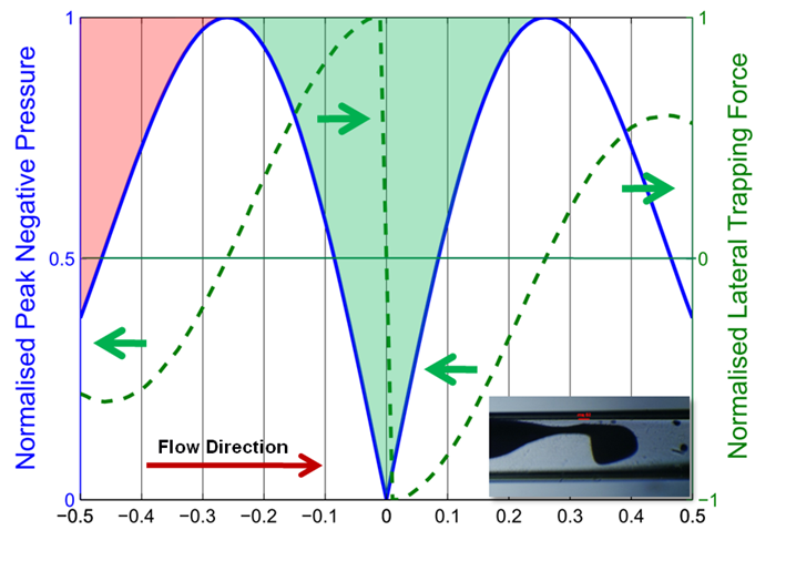
The figure below shows a theoretical plot of the peak negative pressure (blue line) and the resultant normalised trapping force (green). The inset (bottom right) illustrates a large accumulation of microbubbles in a thin capilliary.

A short video showing the clustering of microbubbles in flow within a 200 um capillary tube. Shortly after the start the ultrasound trap is activated and two large clusters can be seen forming. These locations correspond to the approximate lateral positions -0.1mm and 0.2mm. It can be seen that the when the input cluster (left) is large enough drag overcomes the trapping force at this location and it merges with the main cluster. At the end of the video the acoustic trap is de-activated and the microbubbles can be seen dispersing due to the flow in the capillary tube.
In the above video the red line indicates the pressure null of the acoustic trap. In this example a cluster is formed close to the pressure null whilst travelling along the capillary wall. The cluster is not exactly at the pressure null as this is the balance point between the drag force from the fluid flow and the trapping force.
In this example a cluster if formed near the pressure null. Once it is formed the fluid flow is stopped and the ultrasound transducer generating the acoustic trap is translated perpendicular to the capillary, which results in the cluster being manipulated back and forth.
More information can be found in these articles
B. Raiton, J. R. McLaughlan, P. R. Smith, D. M. J. Cowell and S. Freear, Non-invasive cavitation nuclei trap for Histotripsy, In Ultrasonics Symposium (IUS), 2012 IEEE International, pp. 995-998.
B. Raiton, J. R. McLaughlan, S. Harput, P. R. Smith, D. M. J. Cowell and S. Freear, The capture of flowing microbubbles with an ultrasonic trap using acoustic radiation force, Applied Physics Letters, 101 (4), 044102-044102-4. DOI White Rose
See also our list of publicationsread more...